Tuesday, 21 April 2015
Saturday, 11 April 2015
Electrical Engineering project
Low voltage DC motor speed control circuit
Description.
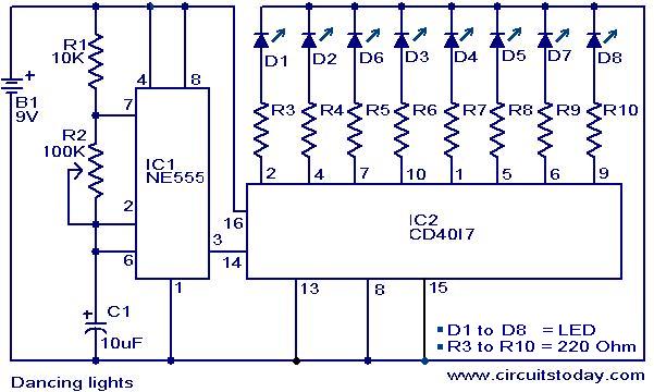
Here is the circuit diagram of a low voltage /low power DC motor speed controller based on the IC TDA 7274 from ST Microelectronics. The IC TDA 7274 is a monolithic integrated DC motor speed controller intended for low voltage/ low power applications. Built in internal voltage reference voltage, wide input voltage range (1.8 t0 6V), high linearity, 700mA output current, excellent temperature stability etc make this IC well suitable for almost all low power DC motor speed control applications.
The motor to be controlled is connected between pin3 (Vs) and pin4 (output) of the IC. Resistor network comprising of R1, R2, and R3 is the section that deals with the speed control. Control pin (pin8) of the IC is connected to the junction of R2 and R3 and the speed of the motor varies linearly according to the position of POT R3. Capacitor C1 rectifies the fluctuations in motor speed and capacitor C2 cancels the motor spikes.
Circuit diagram.

Notes.
- The circuit can be assembled on a Perf board.
- Power supply Vs can be anything between 1.8V to 6V and it must be selected according to the rating s of the motor.
- Maximum output current capacity of this circuit is 700mA.
- TDA7274 must be mounted on a holder.
- POT R3 can be used to vary the motor speed.
Subscribe to:
Posts (Atom)